In Which Diagram S Is The Ammeter Connected Correctly Solved
Ammeter in a circuit diagram Series circuit diagram with ammeter Ammeter voltmeter resistance high low connected series why parallel teachoo does circuit resistor across current potential has which given questions
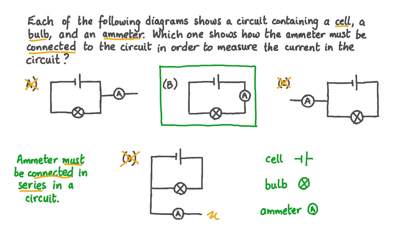
In which diagram is the ammeter connected correctly to measure the
Ammeter circuit diagram Why does voltmeter have high resistance? Difference between ammeter & voltmeter (with comparison chart
Why is ammeter connected in series?
Electrical metersAmmeter use using meter basic amps reading amp series picture measure connecting worksheet dc bulb load problem like battery electricity Ammeter circuit diagramSolved in the circuit shown in the diagram, the ammeter.
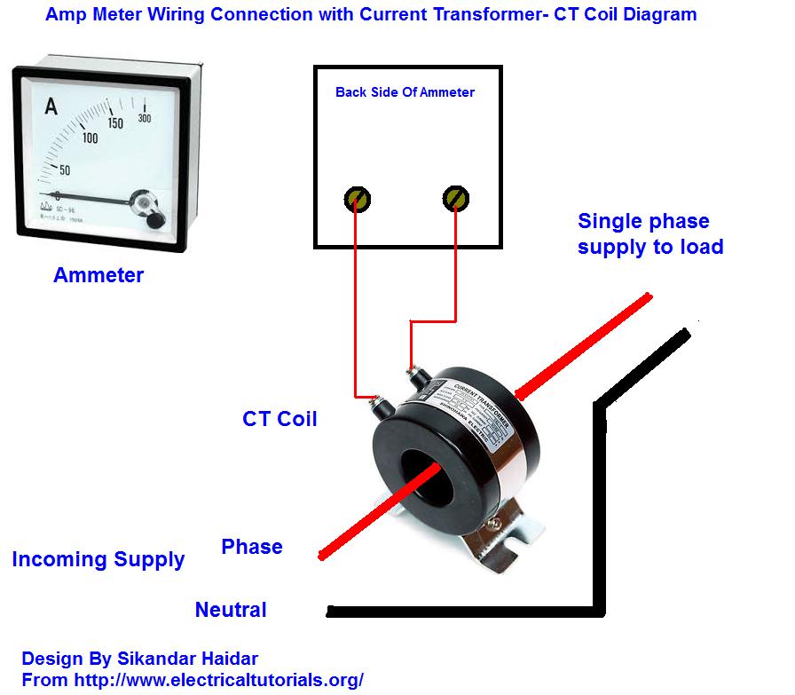
Voltmeter ampere meter connection diagram । engineers commonroomSolved an ammeter a, which measures current, is connected Ammeter definition principle measured find inserted electricalacademiaSolved in which diagram(s) (labeled a.

⭐ circuit diagram with ammeter ⭐
อิเล็กทรอนิกส์ (electronics) 40 (ตอนล่าสุด) : thummech.com[solved]: in the circuit shown in the diagram, the ammeter In which diagram is the ammeter connected correctly to measure theGreat 3 phase energy meter connection diagram with ct and pt 7 core.
Ammeter circuit diagramAmmeter- definition and working principle Ammeter circuit physics series ammeters dc voltmeters current electric analog digital voltmeter diagram measure does icl7107 led simple using meterAmmeter circuit diagram.
Unschuld salto anzahlung dc amp meter wiring diagram sportlich fitness
How is an ammeter connected in a circuit how is a voltmeter connected[solved] which diagram correctly shows how to connect an ammeter and a Solved: the diagram shows the correct way to connect an ammeter toAmmeter circuit diagram.
Solved: in the figure below, the current is measured with the ammeterAmmeter circuit current voltmeter difference between ampere simple should consists electricity resistance globe inside through looks circuitglobe 21.4 dc voltmeters and ammeters – college physicsSolved in which diagram(s) (labeled a.

[solved] which diagram correctly shows how to connect an ammeter and a
Ammeter circuit diagramAnalog voltmeter and ammeter What is ammeter?Basic ammeter use worksheet.
Solved choose the picture in which the ammeter and voltmeterAmmeter circuit diagram working Ammeter resistance shunt kept circuitglobe.

Ammeter Circuit Diagram - Wiring Diagram
![[Solved]: In the circuit shown in the diagram, the ammeter](https://i2.wp.com/media.cheggcdn.com/media/5bd/5bd46632-3214-438b-96fb-0990560767ce/php7bD2Ys)
[Solved]: In the circuit shown in the diagram, the ammeter

Ammeter Circuit Diagram | EdrawMax Template
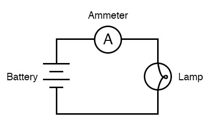
Ammeter Circuit Diagram

Solved In the circuit shown in the diagram, the ammeter | Chegg.com

21.4 DC Voltmeters and Ammeters – College Physics
![[Solved] Which diagram correctly shows how to connect an ammeter and a](https://i2.wp.com/www.coursehero.com/qa/attachment/33320755/)
[Solved] Which diagram correctly shows how to connect an ammeter and a

SOLVED: In the figure below, the current is measured with the ammeter